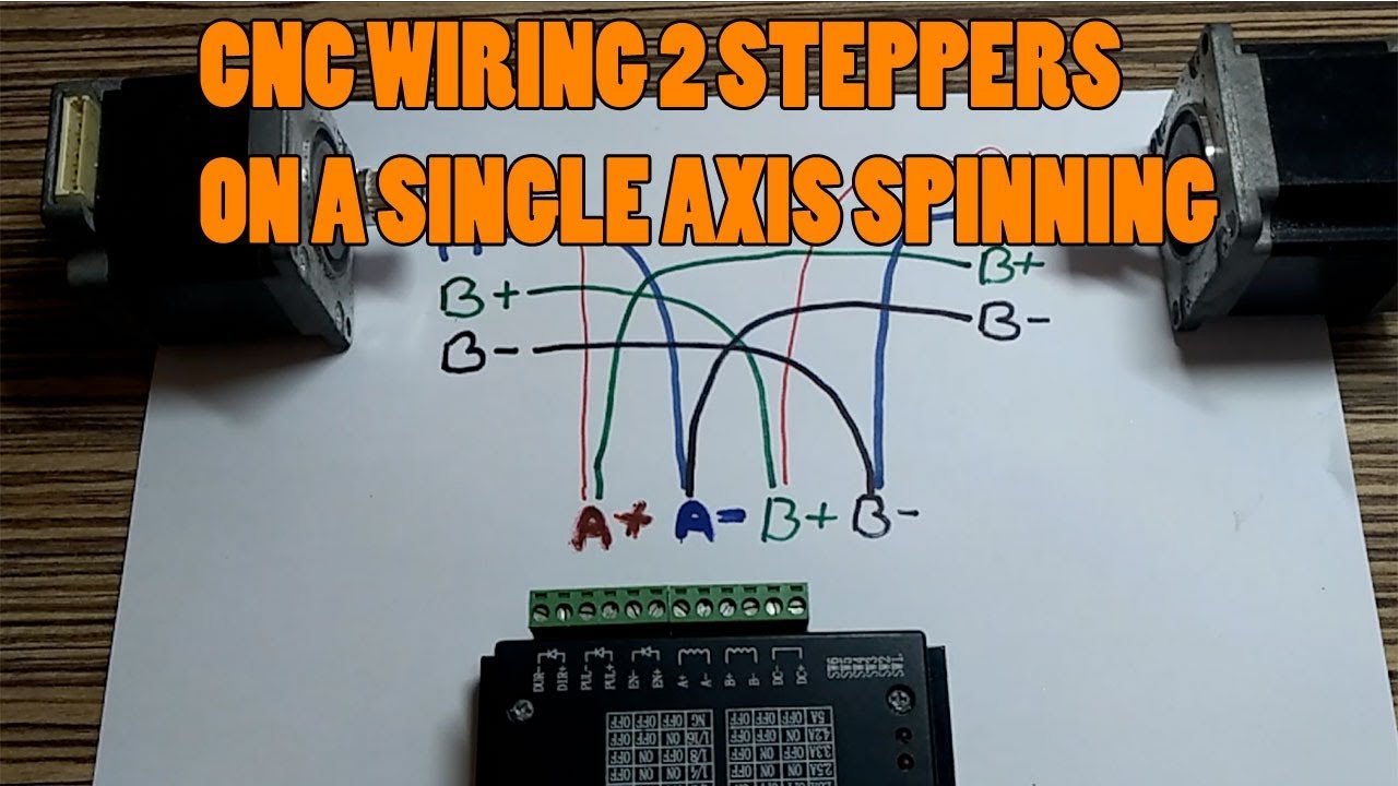
How To Wiring Two Stepper Motors On A Single Axis Spinning In Opposite With Single Driver Youtube
Stepper motors with six wires are unipolar and have one winding per phase like the bipolar steppers but with a center tap. You have to find paired wires of your stepper motor and connect them to drive s a a and b b terminals. Connecting a stepper motor to a buildbotics cnc controller requires properly connecting the four wires from the driver to the right wires on the motor. I ve also connected the wire to the shielding or screening which will eventually go to the ground here. This diagram illustrates proper wiring and what to avoid. This wire will go to the power ground terminal on the stepper driver and screen or shield the direction and pulse coming into the driver boards. Arduino 5v to 5v on the drive arduino digital pin 9 to cw direction on the drive. It cannot drive unipolar stepper motors. One big difference. There are several characteristics that make stepper motors different from one another.
Geckodrive is your source for products and important information regarding step and servo drives.
There are several characteristics that make stepper motors different from one another. This wire will go to the power ground terminal on the stepper driver and screen or shield the direction and pulse coming into the driver boards. Stepper motors with six wires are unipolar and have one winding per phase like the bipolar steppers but with a center tap. Connecting a stepper motor to a buildbotics cnc controller requires properly connecting the four wires from the driver to the right wires on the motor. This diagram illustrates proper wiring and what to avoid. Unfortunately stepper motors come in a variety of configurations and it is not always immediately obvious how to hook them up.
Looking at the diagram above we can assume that the resistance between a1 and ac will be half of that between a1 and a2. I ve also connected the wire to the shielding or screening which will eventually go to the ground here. Unfortunately stepper motors come in a variety of configurations and it is not always immediately obvious how to hook them up. This wire will go to the power ground terminal on the stepper driver and screen or shield the direction and pulse coming into the driver boards. Connecting a stepper motor to a buildbotics cnc controller requires properly connecting the four wires from the driver to the right wires on the motor. Geckodrive is your source for products and important information regarding step and servo drives. From arduino i had to connect only 3 wires. Fortunately most stepper motors can be wired up as bipolar motors. Arduino 5v to 5v on the drive arduino digital pin 9 to cw direction on the drive. Stepper motors with six wires are unipolar and have one winding per phase like the bipolar steppers but with a center tap.
Unfortunately stepper motors come in a variety of configurations and it is not always immediately obvious how to hook them up. Looking at the diagram above we can assume that the resistance between a1 and ac will be half of that between a1 and a2. The internal wiring of these motors looks like this. One big difference. Connecting a stepper motor to a buildbotics cnc controller requires properly connecting the four wires from the driver to the right wires on the motor. Fortunately most stepper motors can be wired up as bipolar motors. I ve also connected the wire to the shielding or screening which will eventually go to the ground here. This diagram illustrates proper wiring and what to avoid. Arduino 5v to 5v on the drive arduino digital pin 9 to cw direction on the drive. You have to find paired wires of your stepper motor and connect them to drive s a a and b b terminals.
Arduino 5v to 5v on the drive arduino digital pin 9 to cw direction on the drive. It cannot drive unipolar stepper motors. Looking at the diagram above we can assume that the resistance between a1 and ac will be half of that between a1 and a2. You have to find paired wires of your stepper motor and connect them to drive s a a and b b terminals. From arduino i had to connect only 3 wires. This diagram illustrates proper wiring and what to avoid. Unfortunately stepper motors come in a variety of configurations and it is not always immediately obvious how to hook them up. I ve just wired a bit of cable between the z axis direction and pulse to the stepper driver. I ve also connected the wire to the shielding or screening which will eventually go to the ground here. The internal wiring of these motors looks like this.
This wire will go to the power ground terminal on the stepper driver and screen or shield the direction and pulse coming into the driver boards. Connecting a stepper motor to a buildbotics cnc controller requires properly connecting the four wires from the driver to the right wires on the motor. There are several characteristics that make stepper motors different from one another. I ve just wired a bit of cable between the z axis direction and pulse to the stepper driver. The internal wiring of these motors looks like this. Looking at the diagram above we can assume that the resistance between a1 and ac will be half of that between a1 and a2. Stepper motors with six wires are unipolar and have one winding per phase like the bipolar steppers but with a center tap. I ve also connected the wire to the shielding or screening which will eventually go to the ground here. From arduino i had to connect only 3 wires. It cannot drive unipolar stepper motors.
I ve just wired a bit of cable between the z axis direction and pulse to the stepper driver. The internal wiring of these motors looks like this. From arduino i had to connect only 3 wires. It cannot drive unipolar stepper motors. I ve also connected the wire to the shielding or screening which will eventually go to the ground here. Stepper motors with six wires are unipolar and have one winding per phase like the bipolar steppers but with a center tap. This wire will go to the power ground terminal on the stepper driver and screen or shield the direction and pulse coming into the driver boards. Arduino 5v to 5v on the drive arduino digital pin 9 to cw direction on the drive. Geckodrive is your source for products and important information regarding step and servo drives. Connecting a stepper motor to a buildbotics cnc controller requires properly connecting the four wires from the driver to the right wires on the motor.